Installation and setup
Installing dependencies
CMake (3.20 or newer), Python3 and an ARM toolchain are required to build the project.
To install the dependencies on Debian Bookworm, run:
apt install cmake python3 python3-venv build-essential gcc-arm-none-eabi libnewlib-arm-none-eabi libstdc++-arm-none-eabi-newlib libusb-1.0-0-dev
Clone the audio-latency-tester repository:
git clone https://github.com/antmicro/audio-latency-tester.git
cd audio-latency-tester
To run the project, it is also required to install following Python packages:
python3 -m venv .venv
source .venv/bin/activate
pip install pyusb libusb click librosa numpy soundfile argparse
Building RP2040 firmware
Install pico-sdk and pico-extras:
git clone --recurse-submodules --branch 2.1.0 https://github.com/raspberrypi/pico-sdk.git
git clone --recurse-submodules --branch sdk-2.1.0 https://github.com/raspberrypi/pico-extras.git
The build system uses environment variables to find these repositories:
export PICO_SDK_PATH=$(pwd)/pico-sdk
export PICO_EXTRAS_PATH=$(pwd)/pico-extras
To build the project, run:
cmake -S . -B build
cmake --build build -j$(nproc)
If the build succeeded, the following files should be present in build directory:
build/audio_out/rp2040-i2s-timestamp.elfbuild/audio_out/rp2040-i2s-timestamp.uf2build/audio_in_pdm/rp2040-i2s-timestamp-audio-in.elfbuild/audio_in_pdm/rp2040-i2s-timestamp-audio-in.uf2
Flashing hardware
Install Picotool
In order to flash the devices, picotool is required.
The installation instructions can be found in this README.
Flashing firmware to the board
The Audio latency tester board consists of 2 independent RP2040 MCUs - one for audio input, other for audio output.
Each of them has to be flashed with the .uf2 file prepared in the previous steps.
Flashing Audio input firmware
Connect MCU-1 USB-C (the port labeled as
USB-C Mics) to your PC. LEDs should light up.
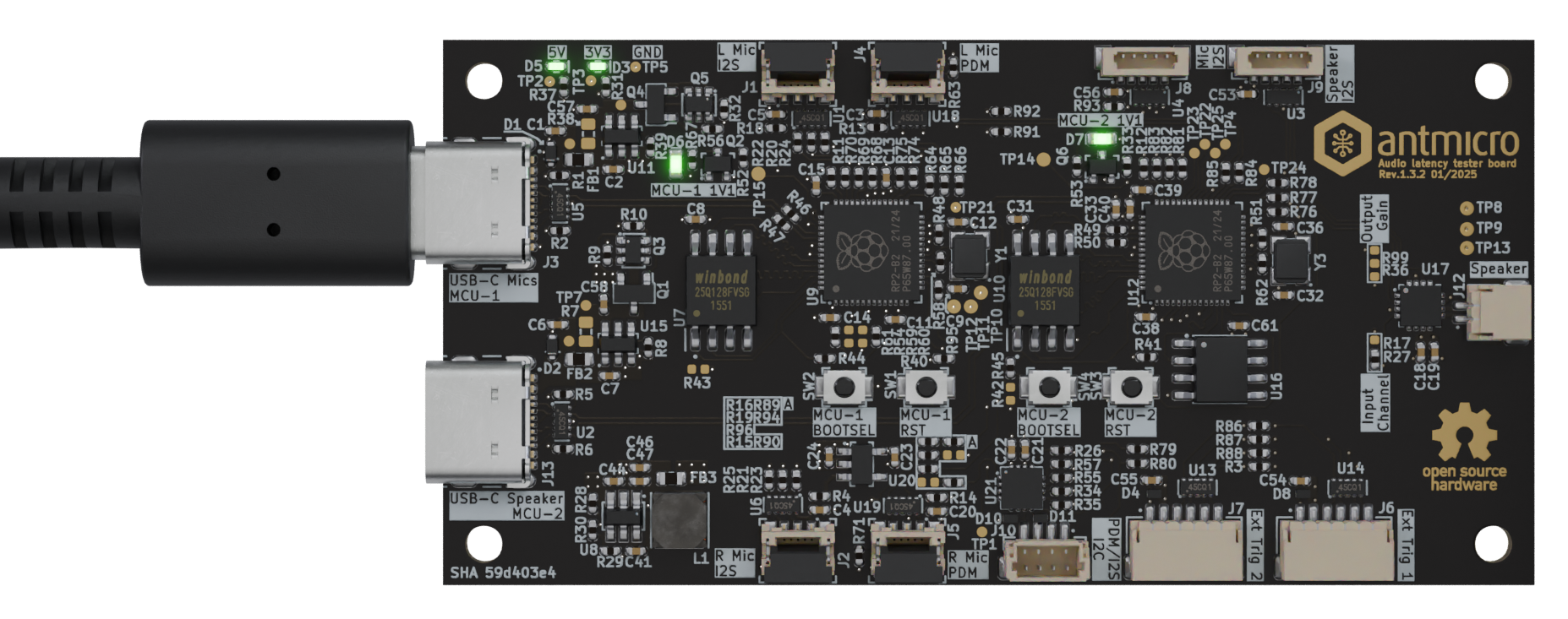
Figure 2 MCU-1 USB-C connection
Press and hold the
MCU-1 BOOTSEL(SW2) button.Press and release the
MCU-1 RST(SW1) button.Release the
MCU-1 BOOTSELbutton.With
lsusb, you should see that the device is recognized as a USB deviceRaspberry Pi RP2 Boot
Bus 001 Device 099: ID 2e8a:0003 Raspberry Pi RP2 Boot
Use
picotoolto flash the device and execute the program immediately:
picotool load -x build/audio_in_pdm/rp2040-i2s-timestamp-audio-in.uf2
Expected output:
Loading into Flash:   [==============================]  100%

The device was rebooted to start the application.
With
lsusb, you should see that the device is recognized as a USB device with IDcafe:4010
Bus 003 Device 012: ID cafe:4010 Raspberry Pi RP2040
Flashing Audio output firmware
Disconnect MCU-1 USB-C port.
Connect MCU-2 USB-C (the port labeled as
USB-C Speaker) to your PC. LEDs should light up.
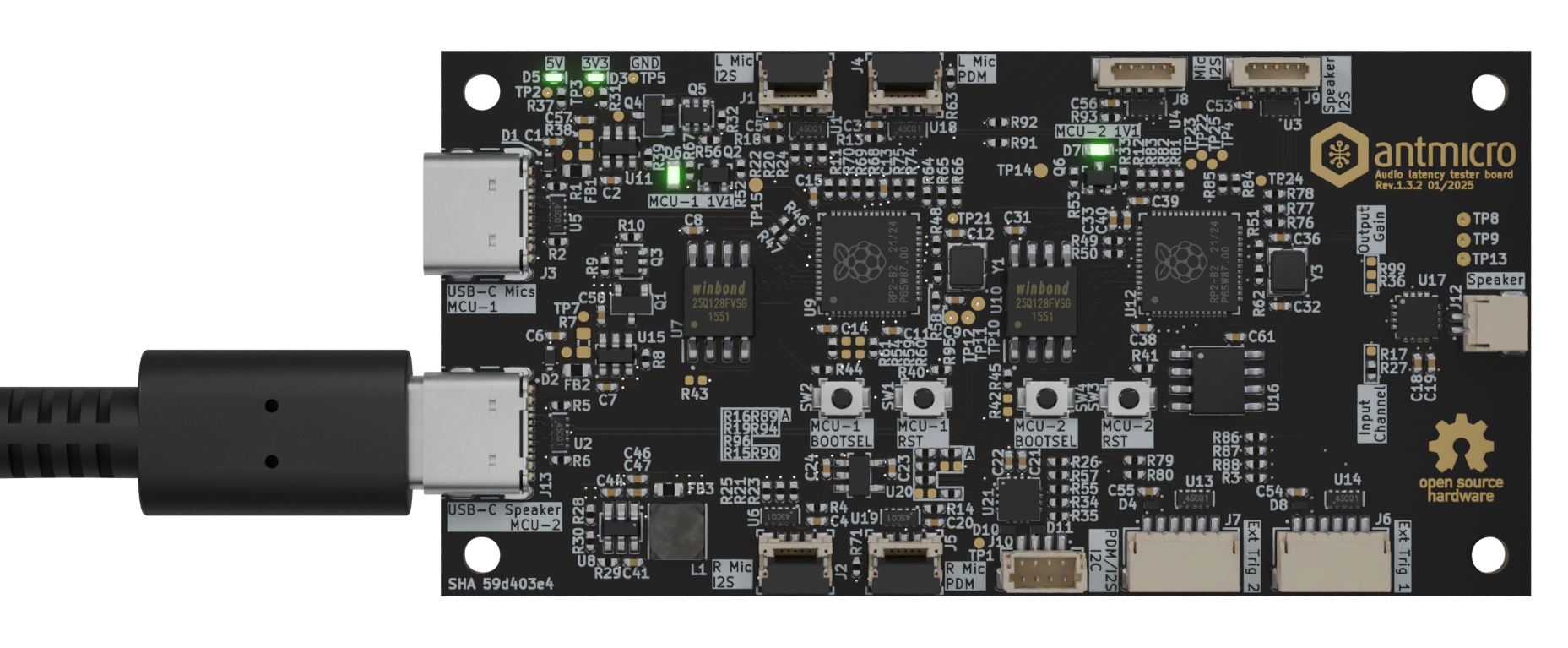
Figure 3 MCU-2 USB-C connection
Press and hold the
MCU-2 BOOTSEL(SW4) button.Press and release the
MCU-2 RST(SW3) button.Release the
MCU-2 BOOTSELbutton.With
lsusb, you should see that the device is recognized as a USB deviceRaspberry Pi RP2 Boot
Bus 001 Device 101: ID 2e8a:0003 Raspberry Pi RP2 Boot
Use
picotoolto flash the device and execute the program immediately:
picotool load -x build/audio_out/rp2040-i2s-timestamp.uf2
With
lsusb, you should see that the device is recognized as a USB device with IDcafe:4011
Bus 003 Device 012: ID cafe:4011 Raspberry Pi RP2040