Hardware setup
A complete setup using the SDI-MIPI Bridge would typically consist of at least 3 devices:
SDI Bridge - Antmicro’s SDI to MIPI CSI-2 Bridge responsible for deserializing SDI data and packeting it with the MIPI CSI-2 protocol,
Transmitter - a device transmitting SDI video data, connected to the SDI input port of the bridge,
Receiver - a device receiving MIPI CSI-2 video data, connected to the MIPI CSI-2 output port of the bridge.
SDI Bridge
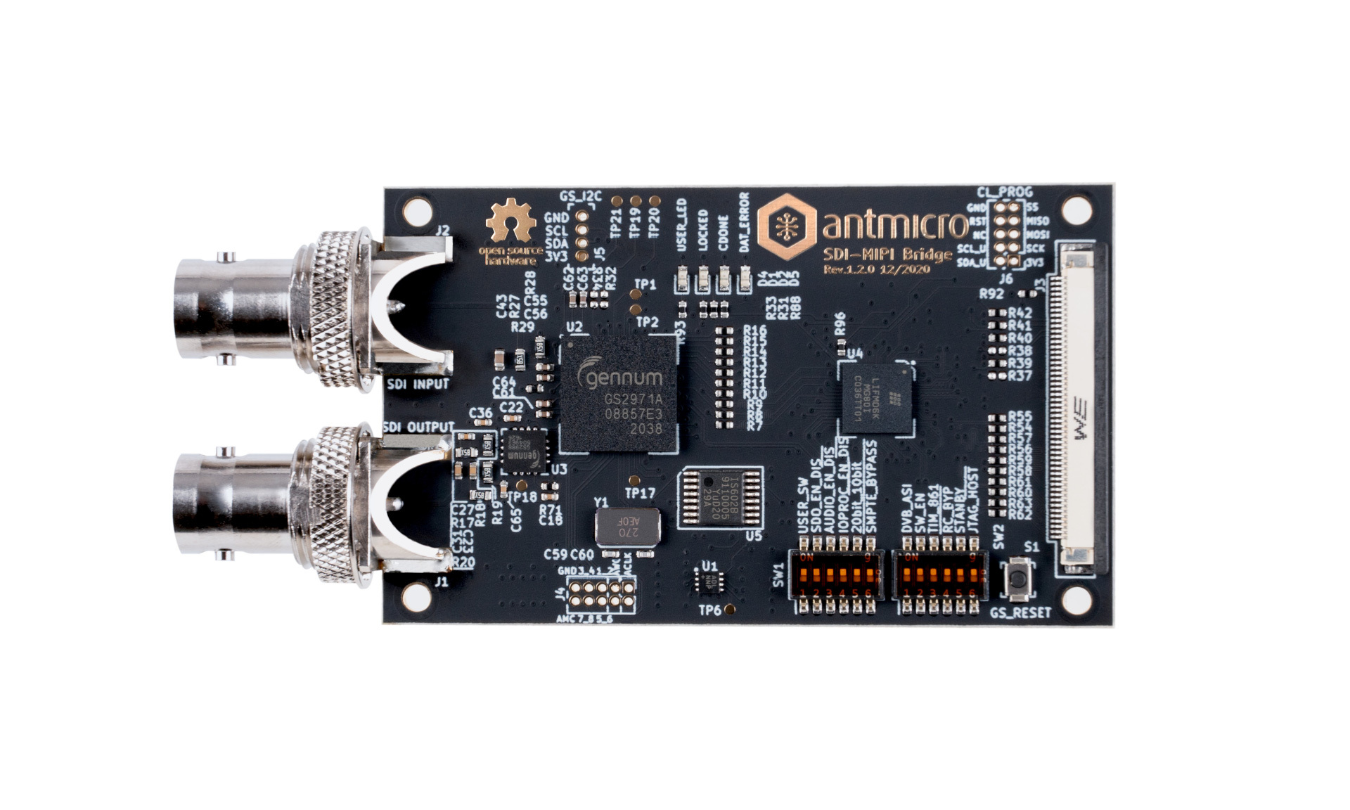
The core part of the setup is the SDI to MIPI CSI-2 Bridge that you can obtain from Antmicro’s partner Capable Robot Components. You can also design and manufacture custom variants and integrated hardware through Antmicro’s engineering services - please refer to the Custom engineering services section to learn more.

Figure 1 SDI to MIPI CSI-2 Bridge, rev. 1.2.0
Key features
Operates at 2.97Gb/s, 2.97/1.001Gb/s, 1.485Gb/s, 1.485/1.001Gb/s and 270Mb/s
Supports SMPTE ST 425 (Level A and Level B), SMPTE ST 424, SMPTE ST 292, SMPTE ST 259-C and DVB-ASI
Integrated SDI adaptive cable equalizer and output loopback connector
I2S de-embedded audio output for up to 8 channels at 48kHz exposed on a 10-pin header
Two 4-lane MIPI D-PHY transceivers at 6 Gbps per PHY exposed on a 50 pin FFC connector
I2C programming and communication interface for the CrossLink FPGA and Semtech SDI deserializer
SPI interface for programming the CrossLink FPGA
User button
2 LED indicators for user purposes
Architecture and operation

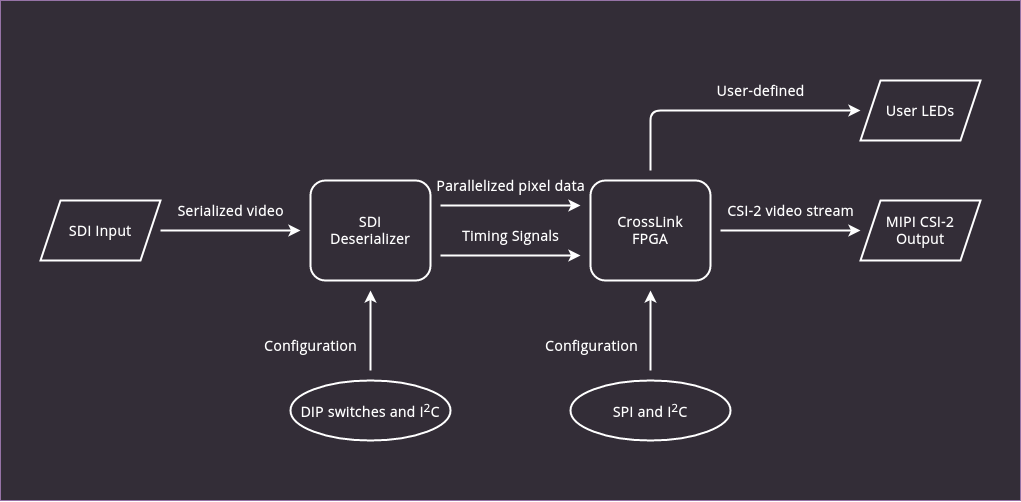
Figure 2 SDI to MIPI CSI-2 Bridge architecture
For video data, the board has an SDI input BNC connector and a MIPI CSI-2 output 50-pin connector, as well as an additional SDI loopback BNC connector.
SDI signal conversion is implemented with the Semtech GS2971A deserializer which passes the parallel 10-bit data to the Lattice CrossLink FPGA. The CrossLink FPGA family targets video bridging and processing applications, with hard MIPI D-PHY interfaces. In this application, it is used to convert parallel data to the MIPI CSI-2 format.
There is also a 10-pin connector on the board which provides audio data extracted from the SDI stream in I2S format. Additionally, the board exposes SPI and I2C interfaces.
SDI deserializer configuration
Due to the board’s wide range of capabilities and possible support for various different configurations there are 12 resitors for configuring the SDI deserializer. A detailed description of their functions is available in the Semtech GS2971A documentation.
Below you can find a short description of each signal with its default setting which should be set in order to make the board work with the software/bitstream setup provided by Antmicro:
Name |
Default |
Notes |
|---|---|---|
USER_SW |
OFF |
Connected to the PB6D input of the Crosslink FPGA. |
SDO_EN |
ON |
Enables/disables the SDI loopback output of GS2971A, which is buffered and exposed on the ‘SDI Output’ BNC. |
AUDIO_EN |
ON |
Enables/disables audio extraction fuctionality of GS2971A. |
IOPROC_EN |
ON |
Enables/disables signal processing features of GS2971A like error correction and level conversion. |
20bit_10bit |
OFF |
Used to select the output bus width. Must be set to low for proper operation on this board. |
SMPTE_BYPASS |
ON |
When ON, GS2971A carries out SMPTE scrambling and I/O processing. When OFF, GS2971A operates in data pass-through mode. |
DVB_ASI |
OFF |
Enables/disables the DVB-ASI mode of GS2971A. |
SW_EN |
OFF |
When OFF, the default state of GS2971A’s SW_EN pin is low. A rising edge (via switch or FPGA GPIO) will cause GS2971A to re-lock on the input video stream. Generally not needed unless the video source has been externally switched between two sources |
TIM_861 |
OFF |
When ON, GS2971A outputs CEA 861 timing signals (HSYNC/VSYNC/DE) instead of H:V:F digital timing signals. |
RC_BYP |
OFF |
When ON, the serial digital output is the re-timed version of the serial input. When OFF, the serial digital output is simply the buffered version of the serial input, bypassing the GS2971A’s internal reclocker. |
STANDBY |
OFF |
When ON, GS2971A is placed in a power-saving mode. No data processing occurs, and the digital I/Os are powered down. |
JTAG_HOST |
OFF |
When ON, the host interface port of GS2971A is configured for JTAG test. When OFF, GS2971A operates normally. |
Board dimensions

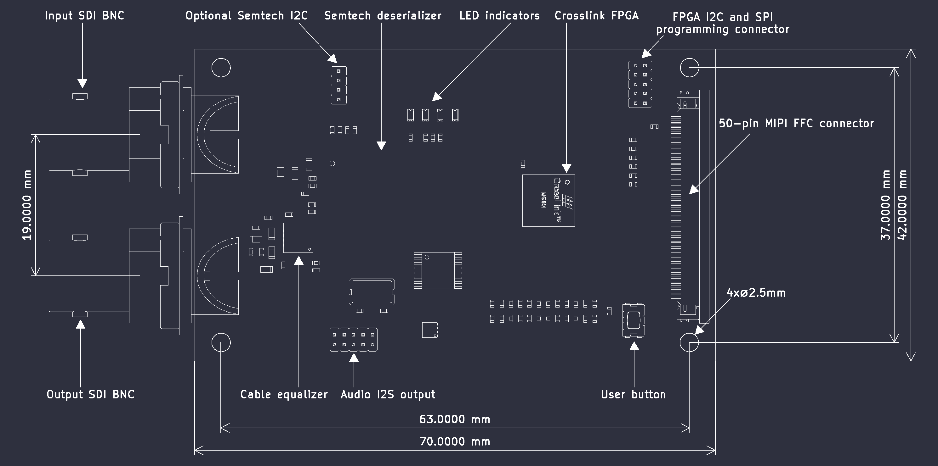
Figure 3 SDI Bridge dimensions - rev.1.3.1
Transmitter
The transmitter is a device (typically a camera) outputting data via the SDI interface. It must be compatible with one of the following available formats:
720p25Hz YUV422,
720p30Hz YUV422,
720p50Hz YUV422,
720p60Hz YUV422,
1080p25Hz YUV422,
1080p30Hz YUV422,
1080p50Hz YUV422,
1080p60Hz YUV422.
Several input devices were tested with the SDI to MIPI Bridge, e.g.:
Atomos Shogun Flame,
Receiver
The receiver is a device capable of receiving data through the MIPI CSI-2 interface. The Software section of this documentation covers support for 3 boards:
Jetson Xavier NX
Jetson TX2
Raspberry Pi CM4
Antmicro provides sources for a Linux distribution configured for SDI Bridge support for these boards. If you need help with making the board work with other edge AI platforms or integrating the SDI interface into your own dedicated device, Antmicro offers Custom engineering services.