Board overview
Jetson Orin Baseboard is an open hardware board design supporting NVIDIA Jetson Orin NX and Orin Nano family of SoMs. The board design files were created in KiCad 8.x. The board is a versatile development kit which can be easily adopted in order to make it usable in commercial applications for autonomous vehicles, industry, agriculture, medicine or space. You can find out more about the Jetson Orin Baseboard in this blog article, or by visiting Antmicro’s portals listed below:
They provide 3D renders and the board stackup definition, as well as an interactive preview of the board schematic.
You can also browse board-specific assets in the GitHub releases section. The assets provided here include PDF schematics and mechanical (STEP) models of the board assemblies in certain revisions.
IO map
A map of on-board connectors, status LEDs, control buttons and I/O interfaces is provided below.
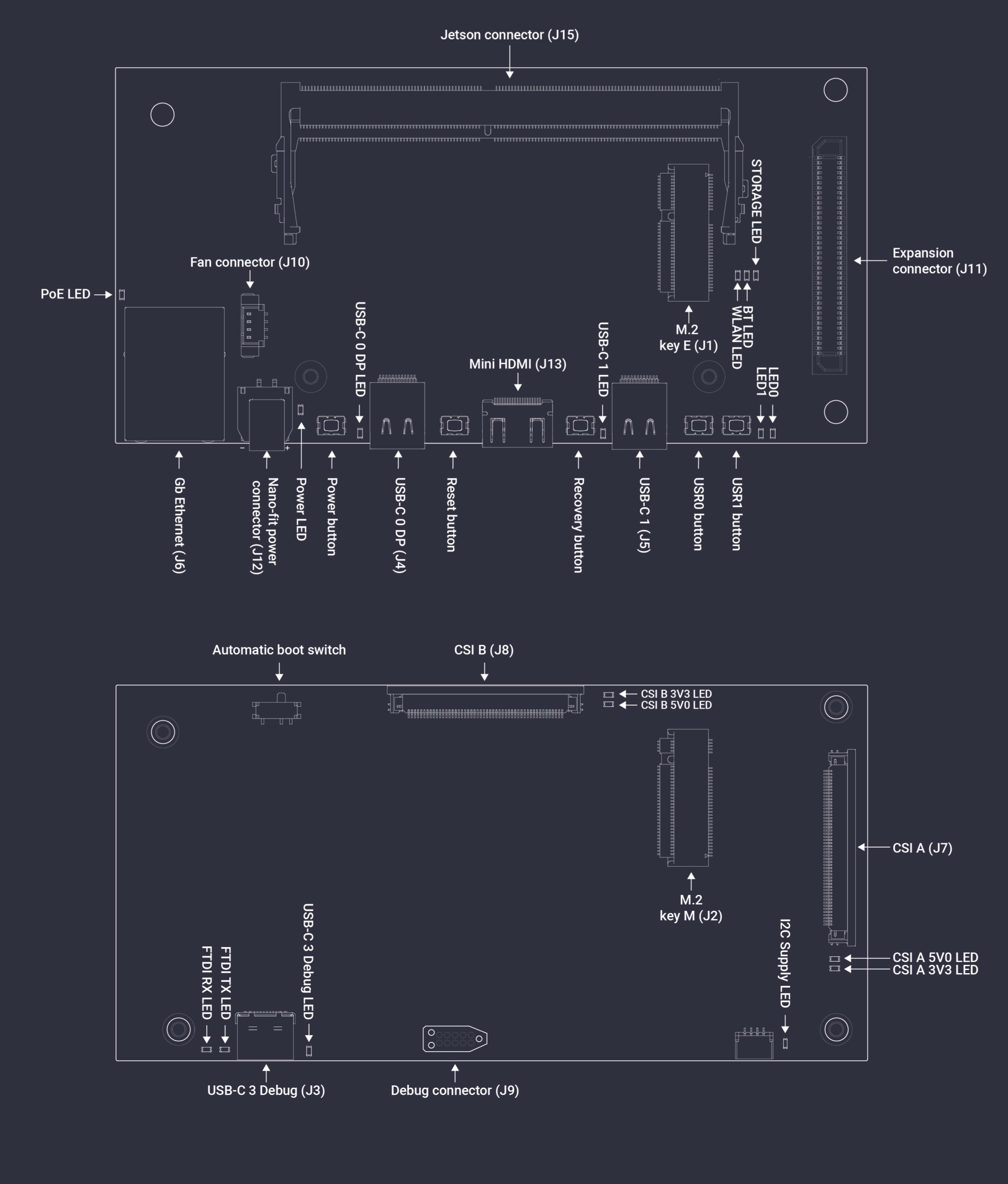
Figure 3 Jetson Orin Baseboard interface map
Power
The board can be powered with the following sources:
1. DC Connector
Jetson Orin Baseboard can be powered with a stable DC voltage via the on-board locking DC connector (J12) with Molex Nano-Fit plug (see the Power Supply section for details related to Nano-Fit power harness assembly).
You can use an external DC adapter for powering the board or a battery pack with rechargeable or non-rechargeable batteries, as long as the provided voltage fits within the accepted range (9-20VDC for board revision >= 1.3.0 and up to 15 V on rev. <= 1.1.7).
In board revision >= 1.3.0, the power supply voltage provided to the SoM is switched between VCC_IN power rail and 5V power rail provided by the on-board step down DC-DC converter depending on the MODULE_ID pin status.
This enables the use of the Jetson Orin NX in “super” mode which requires a minimum power supply voltage of 8V.
If you plan to power the Jetson Orin Baseboard from a battery pack, please note that battery (re-) charging is currently not supported in the design.
Adjusting the power supply scenario for specific battery types and charging strategy can be implemented via a custom modification of the baseboard PCB design.
2. Power over Ethernet
Jetson Orin Baseboard supports PoE++ Type 1-4 (IEEE 802.3bt) and negotiates Power Delivery (PD) with a maximum power budget of 60W.
The board includes an isolated PoE DC/DC converter.
You can power the board via the Gigabit Ethernet port (J6) using a PoE injector or a PoE-capable Ethernet switch.
3. USB-C Power Delivery
USB Power Delivery PD is available on two USB-C ports:
Those ports are maintained by the on-board USB-C Power Delivery controller (Texas Instruments/TPS65988). This controller needs to be configured in order to make it implement one of the desired power source/sink negotiation scenarios.
Note
The recommended power supply voltage negotiated with the USB-C PD controller for power sink mode is 20VDC (15VDC for board revisions <= 1.3.0). If you plan to power up the Jetson Orin Baseboard through the USB PD source, make sure it meets power requirements for stable operation.
USB-C Power Delivery controller configuration
The on-board USB-C Power Delivery controller (Texas Instruments/TPS65988) can be configured for a specific power profile by writing a binary configuration file to an SPI flash.
You can generate your own configuration file with the TPS6598X-CONFIG utility provided by Texas Instruments.
Please refer to the Jetson Orin Baseboard schematics to identify the USB port and power supply rail associated with it to generate a valid power profile setting while using the TPS6598X-CONFIG tool.
Also please refer to the TPS65987DDH and TPS65988DH Host Interface Technical Reference Manual for further details.
There are several ways to write the USB-C PD configuration to the on-board controller:
Via an external SPI Flash programmer connected to the
J9Via the antmicro-jetson-orin-baseboard-tps65988-config tool
From the Jetson Orin SoM BSP (user space)
From the host (PC) via the USB-C (
J3) debug console interface port (in baseboard revisions >= 1.1.9)
If you happen to have some of the most recent baseboard revision (>= 1.1.9), the easiest method to use is flashing from the debug console interface port.
External SPI Flash programmer
1. Collect the hardware
You will need the following pieces of hardware to proceed with writing the USB-C PD configuration file to the SPI Flash:
A computer running Linux (the following procedure has been tested with Ubuntu 23 and Debian 11 distributions)
USB dongle based on FTDI/(FT4232H-56Q) FTDI4232. We suggest using Antmicro’s open hardware Debug Toolkit to simplify the setup (the cable mentioned below connects its J2 straight with Jetson Orin Baseboard’s J9)
10 Pin Tag-Connect TC2050-IDC-NL cable This cable should be connected to the signals from FTDI FT4232 according to the following table:
Tag-Connect TC2050-IDC-NL-050 (pinout) |
FTDI 4232 (pinout) |
|---|---|
1 |
3V3 |
2 |
ADBUS3 (TMS/CS) |
3 |
GND |
4 |
ADBUS0 (TCK/SCLK) |
5 |
GND |
6 |
ADBUS2(TDO/MISO) |
7 |
NC |
8 |
ADBUS1 (TDI/MOSI) |
9 |
GND |
10 |
NC |
2. Prepare the FT4232 dongle
Set the Debug Toolkit Channel A to 3.3V logic with a jumper.
Enable JTAG VCC with a jumper.
Select
SPI/SWDinterface mode for channel A with a jumper.Connect the 10 Pin Tag-Connect cable to the Debug Toolkit assuming the connection mapping specified in the table above (for Antmicro Debug Toolkit - connect to J2 connector).
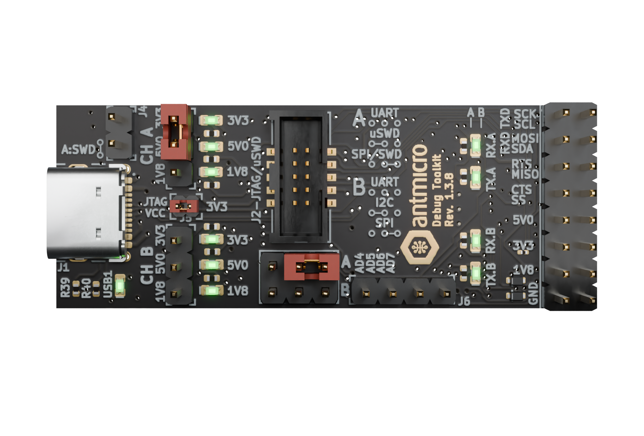
Figure 4 Debug Toolkit Jumper configuration for writing the USB-C PD configuration file.
3. Prepare the PC for flashing
Install the flashrom utility on your host PC. On Debian-based distributions you can use a package manager for that.
sudo apt install flashrom
Adjust the size of the TPS6598 binary configuration file (we named it
config.bin) to match the SPI flash size:
truncate -s 1048576 config.bin
4. Write the configuration
Connect Tag-Connect Plug-of-Nails to the
J9connector on the Jetson Orin Baseboard. Hold the plug in place firmly during the flashing process. The SPI flash will be powered via the programming cable during the flashing process - you do not have to provide your Jetson Orin Baseboard with power.
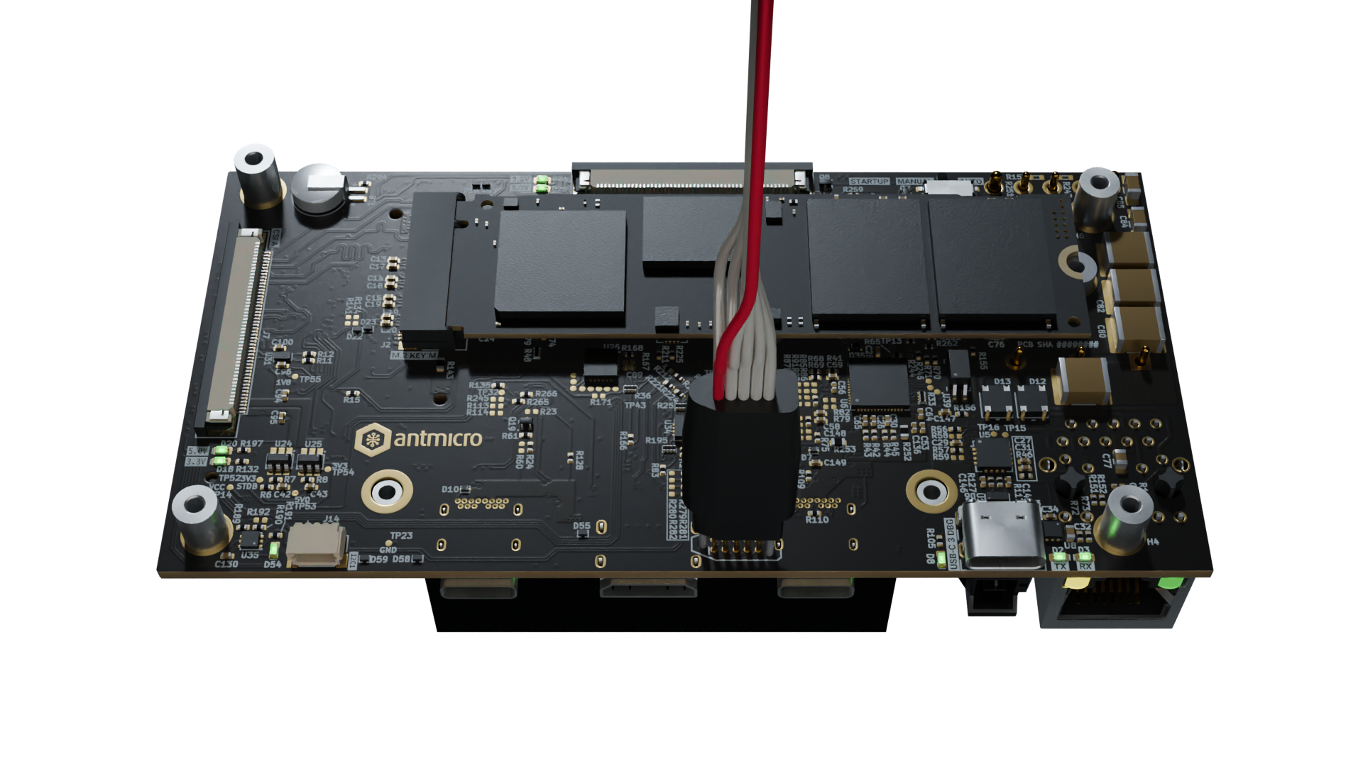
Figure 5 Jetson Orin Baseboard with Tag-Connect plugged for PD controller flashing.
Check if SPI Flash can be detected via Debug Toolkit:
flashrom -p ft2232_spi:type=4232H,port=A,divisor=64 | grep "W25Q80.V"
Expected outcome:
Found Winbond flash chip "W25Q80.V" (1024 kB, SPI) on ft2232_spi.
Write the configuration file to the SPI Flash:
flashrom -p ft2232_spi:type=4232H,port=A,divisor=64 -w config.bin
Expected outcome:
(...)
Reading old flash chip contents... done.
Erasing and writing flash chip... Erase/write done.
Verifying flash... VERIFIED.
You can repeat the previous command to ensure that the binary file has been written successfully:
Expected outcome:
(...)
Warning: Chip content is identical to the requested image.
Erase/write done.
TPS65988-config tool from Jetson Orin user space
The TPS65988-config flashing script can be found in the antmicro-jetson-orin-baseboard-tps65988-config repository.
1. Prepare hardware
To properly execute this script, boot the Jetson Orin Baseboard, and connect to it via the debug console or via SSH.
Since the PD controller is not yet configured at this point, the baseboard has to be powered from either the J12 or via PoE connected to the J6.
Internet connection is also suggested.
2. Install dependencies
Log into Jetson Orin module.
Clone the antmicro-jetson-orin-baseboard-tps65988 repository and install the smbus2 package using pip
git clone https://github.com/antmicro/antmicro-jetson-orin-baseboard-tps65988-config.git
pip3 install smbus2
cd antmicro-jetson-orin-baseboard-tps65988-config
3. Flash the config
Run:
python3 TPS65988_flash.py --erase --write JOBrev1_1_6.bin
Expected outcome:
(...)
Writing 42KB to flash memory...
Write completed 43968 bytes written
The PD Controller has been flashed successfully
Performing cold reset
TPS65988-config tool via the debug console interface port
This option allows for flashing the USB-C Power Delivery controller without SoM or external power.
1. Prepare hardware
Disconnect power supply from the baseboard
Remove Jetson module from the baseboard
Connect a host PC to Jetson Orin Baseboard USB-C Debug Connector (
J3)
2. Install dependencies
On the host PC:
Clone the antmicro-jetson-orin-baseboard-tps65988-config repository and install the smbus2 package with pip
git clone https://github.com/antmicro/antmicro-jetson-orin-baseboard-tps65988-config.git
pip3 install smbus2
cd antmicro-jetson-orin-baseboard-tps65988-config
3. Write the configuration
python3 TPS65988_flash.py --erase --write ./JOBrev1_1_6.bin --ft230x
During the flashing process the D3 LED should light up.
Expected outcome:
(...)
Writing 42KB to flash memory...
Write completed 43968 bytes written
The PD Controller has been flashed successfully
Performing cold reset
Reverting FT230X to UART configuration
The D3 RX LED should turn off indicating end of communication.
Mechanics
The Jetson Orin Baseboard PCB is 120x60 millimeters (WxL) which translates into 4.72x2.36 inch. The overall height of the set depends on the cooling module attached. The base setup with a default cooling module is 37 mm or 1.45 inch tall. The KiCad PCB design files include mechanical layers with dimensions specified for the fastening holes and notable components. The board with the Jetson Module, M.2 storage and cooling module weighs 164g (5.78oz). The mechanical STEP models of the Jetson Orin Baseboard in notable revisions are provided in the releases sections available on GitHub.