Getting started guide
This manual will guide you through the initial setup of the open hardware Jetson Orin Baseboard. It describes the basic steps required to assemble the board with required peripheral accessories, write a compiled Board Support Package (BSP) to the processing module and get it booted. If you want to learn more about the Jetson Orin Baseboard itself, go to the Board Overview section. That section also includes an I/O map that may come in handy when locating interface connectors mentioned in this guide.
Collect the hardware
To get started with the Jetson Orin Baseboard, you’ll need the following hardware:
1. Jetson SoM
The Jetson Orin Baseboard is electrically compatible with the NVIDIA Jetson Orin NX, Jetson Orin Nano family of SoMs including Super modes of those SoMs.
2. Power supply
The Jetson Orin Baseboard supports three power supply scenarios:
USB-C port (
J4) with charger supporting Power Delivery (PD) negotiation. That is the easiest and most recommended solution for starters. The boards produced and distributed by CircuitHub come with pre-configured on-board USB-C Power Delivery controller which enables power sink mode onUSB-C 0port. If you have built the board from scratch, you need to configure the USB-C Power Delivery controller as described in the Board Overview section. You can use a typical smartphone or laptop USB-C charger utilizing Power Delivery protocol with support for 15V or 20V supply.RJ45 (
J6) Ethernet connector using a PoE injector or a PoE-capable Ethernet switch compliant with the IEEE 802.3bt standard.DC locking connector (
J12) which accepts a 2-wire Molex Nano-Fit plug. You can use an off-the-shelf Nano-Fit Cable assembly (Molex/451300203) or build a custom one from a Nano-Fit receptacle (Molex/1053071202) and pre-crimped wires (Molex/797582130). The Jetson Orin Baseboard can be powered with a benchtop PSU or AC/DC wall adapter providing DC voltage. The recommended power supply voltage range for Jetson Orin Baseboard in revision <= 1.1.7 is 9-15 VDC. The recommended power supply voltage range for Jetson Orin Baseboard in revision >= 1.3.0 is 9-20 VDC. If you are using a DC locking connector - please observe the polarity marked in the render below.
Power consumption of the device varies depending on the used SoM version, utilized peripherals and specific application. We recommend using minimum a 30W rated power supply for the Jetson Orin Nano series and minimum 45W for the Jetson Orin NX series.
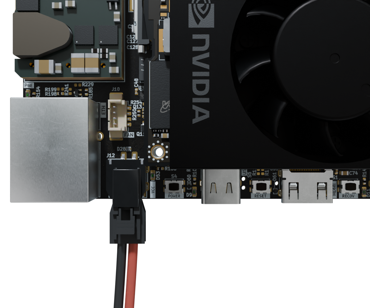
Figure 1 Jetson Orin Baseboard DC power connection with polarity marking (red: vcc, black: gnd).
3. Storage
You should equip the Jetson Orin Baseboard with M.2 NVMe SSD storage with at least 64GB of capacity. That will be the primary storage device from which the SoM will boot.
4. Cooling module
You can use the Jetson Orin compatible cooling fan (Waveshare/24076) as a primary cooling solution when working with the Jetson Orin Baseboard. Using a SoM without any cooling solution attached will make it throttle and eventually reboot or crash the system due to overheating.
5. Fastening bolts
You will need at least one metric M2.5 (5mm long) bolt and a matching screwdriver to fasten the SSD to the baseboard. You may want to use more bolts to fasten the SoM and the baseboard to the baseplate. All mechanical fastening points located on the board support bolts with metric M2.5 thread (ISO 7045).
6. Host PC
You will need a computer running Linux for flashing the reference BSP image to the Jetson Orin SoM installed in the baseboard. The BSP flashing instructions provided below were verified with Debian and Arch based systems. You may need to introduce minor adjustments for other Linux distros.
7. Cabling
SoM Flashing and debug console
You will need two USB-C cables for connecting the SoM flashing port and the debug port located on the Jetson Orin Baseboard to your PC. You should avoid using USB hubs for the flashing interface to get the optimal flashing speed/performance.
Video output
Video output is optional.
Use good quality HDMI 2.1, miniHDMI to HDMI cables with metal body plugs.
Following cables were verified in an anechoic chamber EMI test and are recommended: Ugreen/15514 or Ugreen/15515.
Build your setup
To prepare the Jetson Orin Baseboard for initial usage, follow the steps described below:
1. Install the cooling module
Begin with installing the cooling fan on the Jetson Orin SoM. Make sure the openings carved in the bottom side of the heatsink match the power inductors located on the Jetson Orin SoM. Please refer to the Jetson Cooling Fan product page for details.
2. Install the SoM
Securely attach the NVIDIA Jetson Orin SoM to the J15 connector of the Jetson Orin Baseboard.
Remember to connect the cooling fan plug into the J10 fan receptacle.
Optionally, you can fasten the SoM to the baseboard with two metric M2.5 (5mm long) bolts.
Caution
The baseboard does not support hot-swapping of the SoM. Please disconnect all power sources from the baseboard and wait minimum 10s before removing/inserting the SoM.
3. Install the storage
Install the NVMe M.2 SSD storage in the J2 M.2 (key-M) slot located on the bottom side (i.e opposite side to the SoM) of the Jetson Orin Baseboard.
You need to fasten the SSD with one metric M2.5 (5mm long) bolt to ensure reliable connection.
4. Apply power supply
Pick one of the power supply scenarios described in the Power Supply section.
We recommend using an off-the-shelf USB-C charger connected to the USB-C 0 port (J4) as the easiest option.
Apply power to the board.
Providing valid power supply should cause the VCC (D53) power indicator LED to light up.
5. Connect the debug console
Connect the debug USB-C (J3) port (located on the bottom side, under the power connector) to your PC.
This should get a virtual USB/serial port registered in your system under /dev/ttyUSBx.
You can check the lsusb or dmesg commands to verify if the serial bridge was enumerated properly.
6. Connect the flashing interface
Connect the flashing USB-C (J5 which is the right-most port on the top side of the Jetson Orin Baseboard) to your PC.
This should cause the D11 LED indicator located next to the USB port to light up.
Now you are ready to prepare the BSP flashing image and initialize the flashing process.
At this point you should have 3 USB-C cables connected to the board and providing power supply, debug console in a terminal session, flashing interface.
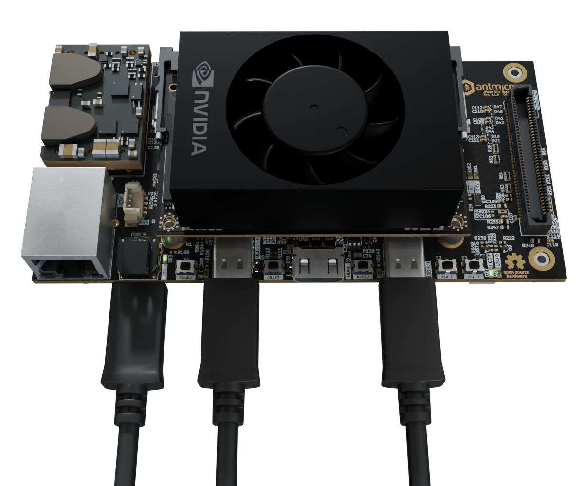
Figure 2 Jetson Orin Baseboard ready for flashing.
Flash the BSP image
Jetson Orin Baseboard comes with a reference BSP image of a Yocto-based system built on top of the meta-antmicro layer. This BSP will let you verify the basic functionality of the board. The following steps will guide you through the process of downloading and flashing a precompiled Board Support Package (BSP) for the Jetson Orin Baseboard.
1. Get the BSP image
First, create a workspace directory that will contain all of the files you will need for flashing:
export WORK="$HOME/antmicro-job-bsp"
mkdir -p $WORK
cd $WORK
Download the BSP image into the previously created workspace directory. Make sure there is no other BSP image already downloaded there. Please use the tabs provided below to pick the reference BSP image suitable for the Jetson Orin SoM variant you plan to use with the baseboard. The latest available reference BSP image is based on JetPack 6.1.
wget https://dl.antmicro.com/projects/nvidia-jetson-orin-baseboard-demo-p3768-0000-p3767-0000.rootfs-20250709101446.tegraflash.tar.gz
wget https://dl.antmicro.com/projects/nvidia-jetson-orin-baseboard-demo-p3768-0000-p3767-0001.rootfs-20250709101437.tegraflash.tar.gz
wget https://dl.antmicro.com/projects/nvidia-jetson-orin-baseboard-demo-p3768-0000-p3767-0003.rootfs-20250709101435.tegraflash.tar.gz
wget https://dl.antmicro.com/projects/nvidia-jetson-orin-baseboard-demo-p3768-0000-p3767-0004.rootfs-20250709102320.tegraflash.tar.gz
wget https://dl.antmicro.com/projects/nvidia-jetson-orin-baseboard-demo-jetson-orin-nano-devkit-nvme.rootfs-20260428121811.tegraflash.tar.gz
Next, unpack the BSP image:
mkdir -p $WORK/bsp
cd $WORK/bsp
tar xvzf $WORK/*.tegraflash.tar.gz
2. Install dependencies
You need to have a device-tree-compiler installed on your machine for the flash tool to work.
On a Debian-like system, you can install it via apt:
sudo apt-get install device-tree-compiler
On an Arch-like system, you can install it via pacman:
sudo pacman -S dtc
3. Disable auto-mounting
When running a Debian-like operating system, you might encounter some difficulties with flashing the board, due to problems with disk auto-mounting. A simple workaround for this issue is to disable auto-mounting for the time being:
gsettings set org.gnome.desktop.media-handling automount false
gsettings set org.gnome.desktop.media-handling automount-open false
4. Enter recovery mode
Make sure that the Jetson Orin Baseboard is connected to a power source and that you have connected the debug console USB and the flashing USB interface to your PC, as described in the Build your setup section. As already mentioned in the Cabling section, you should be entering the recovery mode with direct connection of the flashing USB interface to the PC (i.e. there should be no USB hubs in between). In order to enter the recovery mode, execute the following procedure using buttons located on the top side of the Jetson Orin Baseboard, oriented as shown in the photo above.
Press and release the
POWERbutton located on the top side, next to the DC power jack. The cooling fan on top of the Jetson SoM should start spinning slowly.Press and hold the
RECOV(FORCE_RECOVERY) button located on the top side between the HDMI port and the right-most USB-C connector.Press and release the
RESETbutton located on the top side between the HDMI port and the left-most USB-C connector.Release the
RECOVbutton. The SoM cooling fan will now start spinning faster.
On the host PC, you should now see the following new USB device being detected (e.g. via lsusb):
lsusb | grep -i nvidia
# Bus 001 Device 026: ID 0955:7523 NVIDIA Corp. APX
The Jetson SoM will stay in the recovery mode for ~45s and then it will make an attempt to boot up. If needed, repeat the procedure to force the SoM back into recovery mode.
5. Open debug console
Whenever developing with the Jetson Orin Baseboard, it always makes sense to have a terminal hooked to the Debug UART on your host PC.
You can use any serial port terminal emulator for that, but we’ll use picocom in this guide.
Make sure that the debug console USB is connected to your host PC and the USB-serial converter is enumerated:
lsusb -d 0403:
# Bus 001 Device 118: ID 0403:6015 Future Technology Devices International, Ltd Bridge(I2C/SPI/UART/FIFO)
sudo dmesg | grep FTDI
# [1740634.745814] usb 1-4: FTDI USB Serial Device converter now attached to ttyUSB0
Run the terminal:
sudo picocom -b 115200 /dev/ttyUSB0
You should keep the picocom terminal open in a separate window/tab throughout board flashing.
That will give you an insight into the progress and debug log messages displayed during the process.
6. Flash the board
Open another terminal instance on your PC and navigate to the directory which holds the downloaded and unpacked BSP, as described in the Get the BSP image section.
cd $HOME/antmicro-job-bsp/bsp
Make sure your SoM remains in the recovery mode. Then, execute the flashing script from the same directory:
sudo ./initrd-flash
Be patient, as flashing might take a while (up to 30min). When the flashing succeeds, you should see a log similar to the one below:
Starting at 2024-07-05T11:43:56+00:00
Machine:       p3509-a02-p3767-0000
Rootfs device: nvme0n1p1
Found Jetson device in recovery mode at USB 1-8
== Step 1: Signing binaries at 2024-07-05T11:43:56+00:00 ==
== Step 2: Boot Jetson via RCM at 2024-07-05T11:44:09+00:00 ==
Found Jetson device in recovery mode at USB 1-8
== Step 3: Sending flash sequence commands at 2024-07-05T11:44:12+00:00 ==
Waiting for USB storage device flashpkg from e3340a08...........[/dev/sdc]
Device size in blocks: 262144
== Step 4: Writing partitions on external storage device at 2024-07-05T11:44:57+00:00 ==
Waiting for USB storage device nvme0n1 from e3340a08...[/dev/sdc]
Creating partitions
  [02] name=kernel start=0 size=131072 sectors
  [03] name=kernel-dtb start=0 size=896 sectors
  [04] name=reserved_for_chain_A_user start=0 size=65536 sectors
  [05] name=kernel_b start=0 size=131072 sectors
  [06] name=kernel-dtb_b start=0 size=896 sectors
  [07] name=reserved_for_chain_B_user start=0 size=65536 sectors
  [08] name=recovery start=0 size=163840 sectors
  [09] name=recovery-dtb start=0 size=1024 sectors
  [10] name=RECROOTFS start=0 size=614400 sectors
  [11] name=esp start=0 size=131072 sectors
  [12] name=recovery_alt start=0 size=163840 sectors
  [13] name=recovery-dtb_alt start=0 size=1024 sectors
  [14] name=esp_alt start=0 size=131072 sectors
  [01] name=APP (fills to end)
Writing partitions
  Writing boot.img (size=37214208) to /dev/sdc2 (size=67108864)...
  Writing kernel_tegra234-p3767-0000-antmicro-job.dtb (size=333342) to /dev/sdc3 (size=458752)...
  Writing boot.img (size=37214208) to /dev/sdc5 (size=67108864)...
  Writing kernel_tegra234-p3767-0000-antmicro-job.dtb (size=333342) to /dev/sdc6 (size=458752)...
  Writing esp.img (size=67108864) to /dev/sdc11 (size=67108864)...
  Writing nvidia-jetson-orin-baseboard-demo.ext4 (size=59055800320) to /dev/sdc1 (size=255237365248)...
[OK: /dev/sdc]
== Step 5: Waiting for final status from device at 2024-07-05T12:13:37+00:00 ==
Waiting for USB storage device flashpkg from e3340a08...[/dev/sdc]
Final status: SUCCESS
Successfully finished at 2024-07-05T12:13:41+00:00
Host-side log:              log.initrd-flash.2024-07-05-11.43.56
Device-side logs stored in: device-logs-2024-07-05-11.43.56
Common Issue:
When a device is connected through a USB hub, the initrd-flash script may not recognize it, and it can get stuck displaying “Waiting for Jetson to appear on USB…….”.
To verify whether the baseboard is directly connected to a root hub, use the lsusb -vt command.
Note that some USB ports on your PC motherboard USB may also be internally connected through a hub.
7. Login
After successful flashing, the SoM should reboot and you should see the booting log in the debug console. The SoM should boot up to the login screen visible in the debug console. The reference BSP comes with a preconfigured root account. To log in to the console, connect to the board via UART, turn on the power, and wait for the board to boot. When it successfully boots, you will be asked for login and password:
p3509-a02-p3767-0000 login:
Note
Please note that the login prompt may differ depending on the SoM and the BSP version you used for flashing.
Use the following login credentials to get access to the system:
login: root
password: root