Getting started guide
This manual will guide you through the initial setup of the open hardware COM Express 7 Baseboard. It describes the basic steps required to assemble the board with required peripheral accessories, write a compiled Board Support Package (BSP) to the processing module and get it booted. If you want to learn more about the COM Express 7 Baseboard itself, go to the Introduction section. That section also includes an I/O map that may come in handy when locating interface connectors mentioned in this guide.
Collect the hardware
To get started with the COM Express 7 Baseboard, you’ll need the following hardware:
1. COM Express 7 SoM
The COM Express 7 Baseboard is compatible with COM Express Type 7 modules. The provided reference BSP has been developed for SolidRun LX2160A (SRX2160S01D00GE064V21C0).
2. RAM modules
You will need 2 SO-DIMM DDR4 RAM modules. Check the list of tested modules, to help you choose appropriate RAM modules.
3. Power supply
The COM Express 7 Baseboard supports two power supply scenarios:
More details in Power supply chapter.
4. Fastening bolts
You will need five metric M2.5 (5mm long) bolts and a matching screwdriver to mount the SoM to the baseboard. All mechanical fastening points located on the board support bolts with metric M2.5 thread (ISO 7045).
5. Micro SD card
Micro SD card with capacity of at least 4GB is needed, to transfer the BSP image to the baseboard.
6. Host PC
You will need a computer running Linux for flashing the reference BSP image to the SD card. The BSP flashing instructions provided below were verified with Debian based systems. You may need to introduce minor adjustments for other Linux distributions.
7. SD card reader
You will need to be able to connect the micro SD card to your PC. If your PC doesn’t have an integrated SD card reader, you will need an external one.
8. Cabling
You will need a USB-C cable for connecting your PC to the USB-C port (J3) located on the baseboard.
This connection will provide access to the SoM’s terminal on your PC.
Ethernet cable will be needed to provide internet connection to the COM Express 7 Baseboard via (J1A).
Flash the SD card with system image
1. Download a pre-built snapshot
Download this pre-built snapshot image.
NOTE: This is a stock BSP, which doesn’t support all functionalities of the COM Express 7 Baseboard.
2. Write the BSP image to the SD card
Plug the micro SD into your Linux PC. The following assumes that the micro SD is added as /dev/sdX and all it’s partitions are unmounted. In the terminal, run sudo mount, to check if the SD card is mounted. It can appear as /dev/mmcblk0p1 or /dev/sdb1 or similar. If partitions are mounted, unmount them first: sudo umount <mount point> (eg. sudo umount /dev/sdc1).
Now the image can be flashed to the SD card.
Use this command for writing the image to an SD card (remember to use proper path to the BSP image and SD card):
sudo xz -dc lx2160a_....img.xz | sudo dd of=/dev/sdX bs=4M conv=fsync.
Build your setup
To prepare the COM Express 7 Baseboard for initial usage, follow the steps described below:
1. Install the RAM modules
Begin with installing the RAM modules on the COM Express 7 SoM.
2. Install the SoM
Securely attach the COM Express 7 SoM to the J12 connector of the COM Express 7 Baseboard.
Fasten the SoM to the baseboard with five metric M2.5 (5mm long) bolts.
Remember to connect the cooling fan plug into the J11 fan receptacle.
3. Insert micro SD card
Insert the micro SD card containing the BSP, to the COM Express 7 Baseboard micro SD card slot (J15).
4. Select boot source
Configure the SW1 switch on the COM Express 7 SoM as shown on the image bellow.
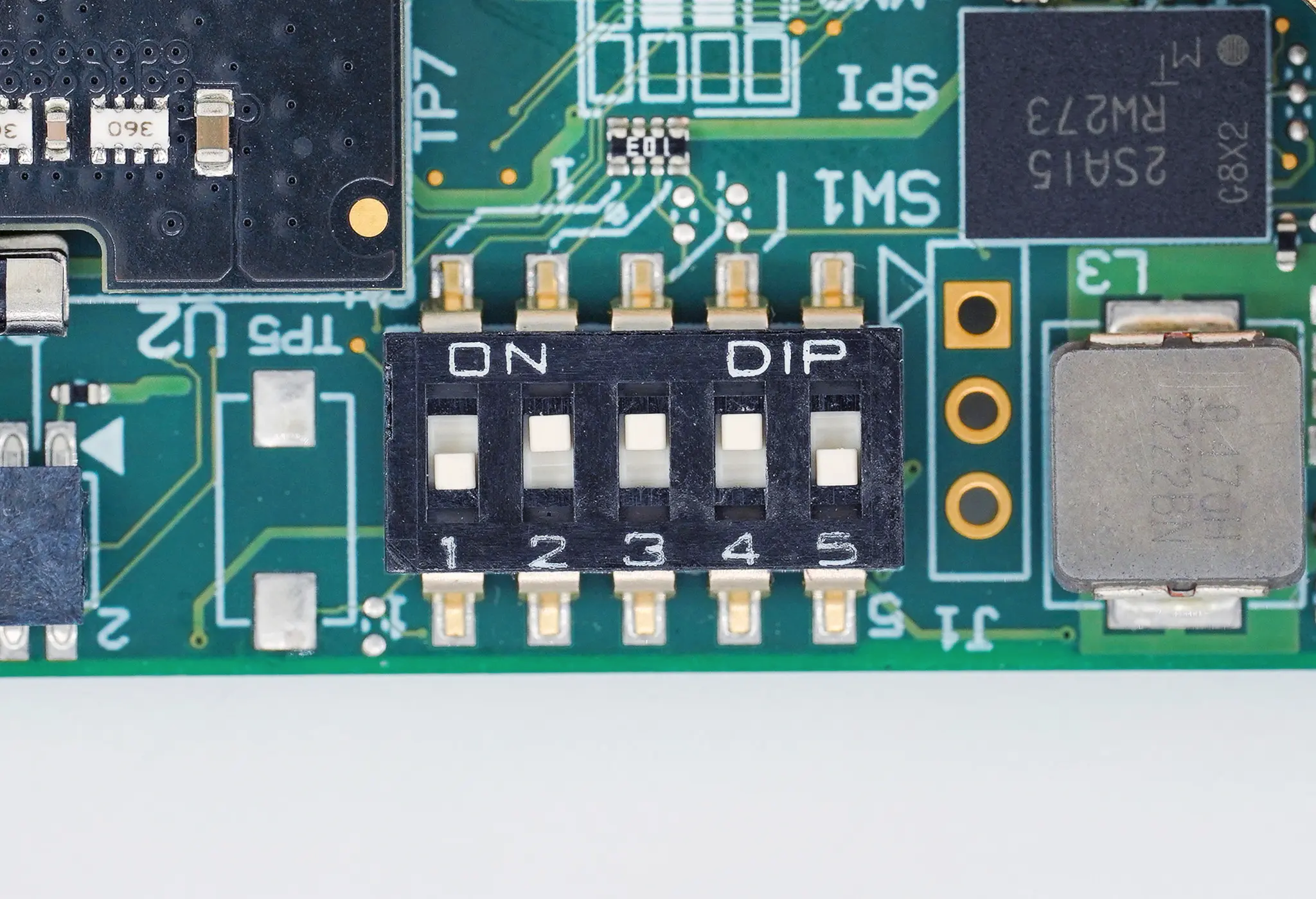
Figure 2 COM Express 7 boot source configured to SD card
Switch 1 |
Switch 2 |
Switch 3 |
Switch 4 |
Switch 5 |
|---|---|---|---|---|
OFF |
ON |
ON |
ON |
x |
5. Connect the Ethernet port.
Connect the COM Express 7 Baseboard to the internet network using RJ45 cable connected to J1A Ethernet port.
6. Connect the debug console
Connect the debug USB-C (J3) port to your PC.
This should get a virtual USB/serial port registered in your system under /dev/ttyUSBx.
You can check the lsusb or dmesg commands to verify if the serial bridge was enumerated properly.
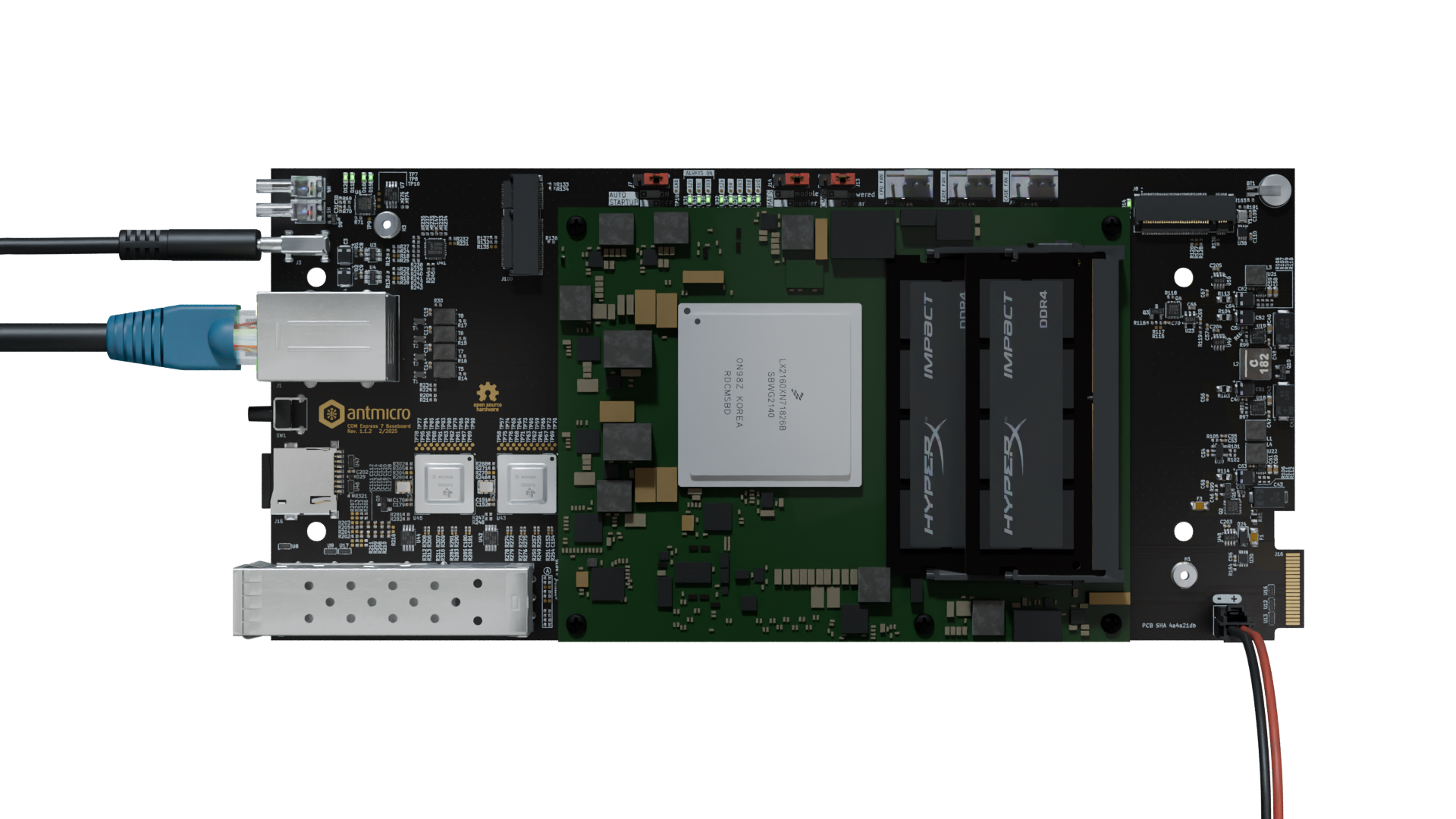
Figure 3 COM Express 7 Baseboard ready for flashing (SoM heat sink and fan not shown).
Flash the BSP image
The following steps will guide you through the process of flashing a precompiled Board Support Package (BSP) for the COM Express 7 Baseboard.
1. Open debug console
Whenever developing with the COM Express 7 Baseboard, it always makes sense to have a terminal hooked to the Debug UART on your host PC.
You can use any serial port terminal emulator for that, but we’ll use picocom in this guide.
Make sure that the debug console USB is connected to your host PC and the USB-serial converter is enumerated:
lsusb -d 0403:
# Bus 001 Device 118: ID 0403:6015 Future Technology Devices International, Ltd Bridge(I2C/SPI/UART/FIFO)
sudo dmesg | grep FTDI
# [1740634.745814] usb 1-4: FTDI USB Serial Device converter now attached to ttyUSB0
Run in the terminal:
sudo picocom -b 115200 /dev/ttyUSB0
2. Apply power
Pick one of the power supply scenarios described in the Power Supply section.
We recommend using the DC locking connector (J6).
Apply power to the board.
Providing valid power supply should cause the (D18) power indicator LED to light up green.
(That is if auto startup is enabled, otherwise you need to press the SW1 power button. More on that in the Power supply chapter.)
The SoM should start booting up, and you should see booting information on the picocom console.
3. Flash to eMMC
Stop the u-boot count down by clicking any key in the picocom console.
To flash to eMMC run the following commands (it will wipe your data on the eMMC device).
load mmc 0:1 0xa4000000 ubuntu-core.img
mmc dev 1
mmc write 0xa4000000 0 0xd2000
Boot the machine by running boot
4. Login
The SoM should boot up to the login screen visible in the debug console. The reference BSP comes with a preconfigured root account.
Use the following login credentials to get access to the system:
localhost login: root
password: root
5. Finalize configuration
Using SW1 switch on the COM Express 7 SoM, configure it to boot from eMMC (change switch 4 to OFF), as shown on the image bellow.

Figure 4 COM Express 7 boot source configured to eMMC
Switch 1 |
Switch 2 |
Switch 3 |
Switch 4 |
Switch 5 |
|---|---|---|---|---|
OFF |
ON |
ON |
OFF |
x |
Remove the micro SD card from the baseboard (this will make it easier to find the path for eMMC).
Check location of the eMMC:
lsblk | grep mmcblk. It should show up asmmcblkX, whereXis an integer.Run
fdisk /dev/mmcblkX.Recreate the first partition by deleting it and then creating a new partition that starts at block 131072 and extends to the end of the drive (or less depending on your needs).
Write the new partition, when prompted
Do you want to remove the signature?, answer withNo.Run
resize2fs /dev/mmcblkXp1.
Example execution of these commands is shown bellow (when no command was given, Enter was pressed).
root@localhost:~# lsblk | grep mmcblk
mmcblk1      179:32   0 59.2G  0 disk
└─mmcblk1p1  179:33   0  350M  0 part /
mmcblk0boot0 179:64   0    4M  1 disk
mmcblk0boot1 179:96   0    4M  1 disk
root@localhost:~# fdisk /dev/mmcblk1

Welcome to fdisk (util-linux 2.37.2).
Changes will remain in memory only, until you decide to write them.
Be careful before using the write command.

This disk is currently in use - repartitioning is probably a bad idea.
It`s recommended to umount all file systems, and swapoff all swap
partitions on this disk.

Command (m for help): d

Selected partition 1
Partition 1 has been deleted.

Command (m for help): p
Disk /dev/mmcblk1: 59.22 GiB, 63585648640 bytes, 124190720 sectors
Units: sectors of 1 * 512 = 512 bytes
Sector size (logical/physical): 512 bytes / 512 bytes
I/O size (minimum/optimal): 512 bytes / 512 bytes
Disklabel type: dos
Disk identifier: 0x30303030

Command (m for help): n
Partition type
   p   primary (0 primary, 0 extended, 4 free)
   e   extended (container for logical partitions)
Select (default p):

Using default response p.
Partition number (1-4, default 1):
First sector (2048-124190719, default 2048): 131072
Last sector, +/-sectors or +/-size{K,M,G,T,P} (131072-124190719, default 124190719):

Created a new partition 1 of type 'Linux' and of size 59.2 GiB.
Partition #1 contains a ext4 signature.

Do you want to remove the signature? [Y]es/[N]o: N

Command (m for help): w

The partition table has been altered.
Syncing disks.

root@localhost:~# resize2fs /dev/mmcblk1p1
resize2fs 1.46.5 (30-Dec-2021)
Filesystem at /dev/mmcblk1p1 is mounted on /; on-line resizing required
old_desc_blocks = 3, new_desc_blocks = 474
The filesystem on /dev/mmcblk1p1 is now 62029824 (1k) blocks long.
Run
dhclientin order to enable internet access.Update the RTC clock by running
ntpdate pool.ntp.organd thenhwclock -w.Run
apt-get update && apt-get upgrade -yand then populate the root filesystem as you wish.