Peripherals
Selection jumpers
Master Attached Flash Sharing location selection
MAFS location can be set to be on
moduleor oncarrier, using (J14) jumper. During normal operation, it is set tomodule.Clear CMOS
Using (
J13) jumper, RTC on COM Express 7 can be cleared. During normal operation, it is set topowered, which provides power to the RTC.
Jumpers positions for normal operation are shown on the render bellow.
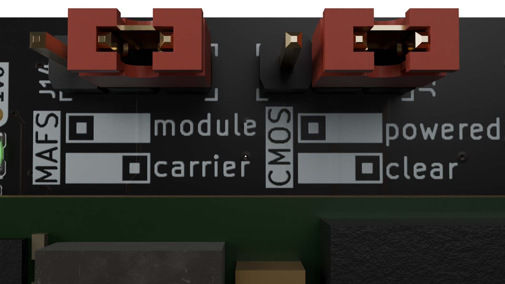
Figure 7 COM Express 7 Baseboard MAFS and CMOS jumpers default configuration.
Fan control
CPU fan (
J11connector) is controlled by the COM Express 7 SoM.Case fans (
J10andJ9connectors) can either share PWM speed control with CPU fan or be individually controlled byADT7476AARQZ(U24).
Board temperature measurement
Board temperature can be monitored with ADT7476AARQZ (U24) in three locations on the COM Express 7 Baseboard, using internal to the IC temperature sensor and two external sensors: (Q9) and (Q10). Their location is shown on the picture bellow.
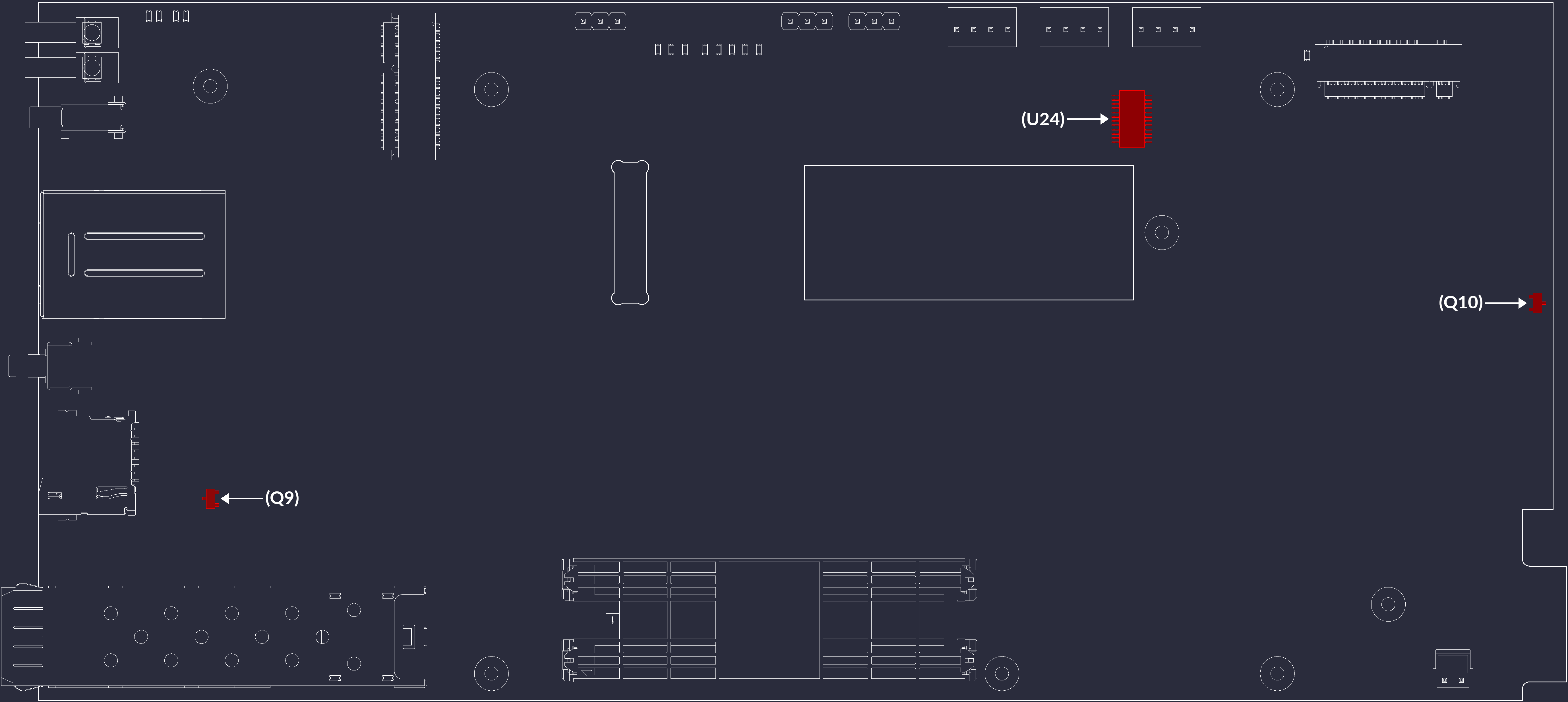
Figure 8 COM Express 7 Baseboard location of temperature sensors.
SFI / KR
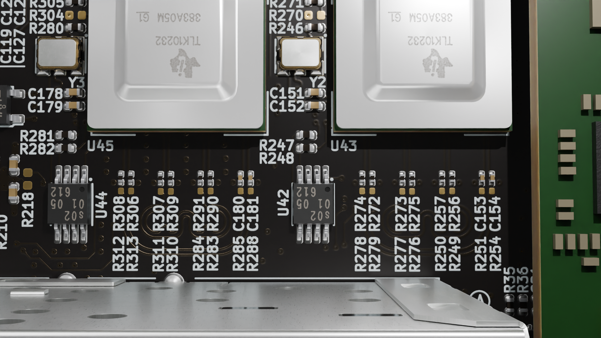
1 HS channel needs to be configured (e.g. CH A) for 10G-KR, configure the other HS channel for XFI per the attached instructions, and use Data Switch to connect CH A to CH B (DST_CONTROL_1/2 registers) (attached instructions).
By using OR resistors, SFI can be directly connected to 10GBase-KR pins on COM Express Type 7, eliminating the need for the TLK10232CTR ICs. This configuration is intended for modules that support SFI-compatible interfaces on 10GBase-KR pins, such as the SolidRun LX2160A.

10GbE on backplane connector
If LX2160A SoM is used, PCIe B3x4 on the backplane connector (J16) can be configured as 10G-KR.
GPIO Expanders
Two PCA9539AHF GPIO expanders are connected to the I2C bus 1 of the SoM:
Expander at Address
0x74(U41)
Pin |
Function |
Details |
|---|---|---|
P0_0 |
RGB LED - Green |
|
P0_1 |
RGB LED - Blue |
|
P0_2 |
RGB LED - Red |
|
P0_3 |
USB Power Enable - |
( |
P0_4 |
USB Power Enable - |
( |
P0_5 |
|
PCIe Redriver / OCuLink |
P0_6 |
|
Backplane Connector ( |
P0_7 |
|
Backplane Connector ( |
Expander at Address
0x75(U5)
Pin |
Function |
Details |
|---|---|---|
P0_0 |
SFP0 LED - Yellow |
|
P0_1 |
SFP0 LED - Green |
|
P0_3 |
SFP1 LED - Yellow |
|
P0_4 |
SFP1 LED - Green |
|