Power supply
Power input connectors
The COM Express 7 Baseboard supports two power supply scenarios:
DC locking connector(J6) which accepts a 2-wireMolex Nano-Fitplug.This is the easiest and most recommended solution for starters. You can use an off-the-shelf Nano-Fit Cable assembly (Molex/451300203) or build a custom one from a Nano-Fit receptacle (Molex/1053071202) and pre-crimped wires (Molex/797582130). The COM Express 7 Baseboard can be powered with a benchtop PSU or AC/DC wall adapter providing 12V DC with at least 60W. If you are using a DC locking connector - please observe the polarity marked in the render below.
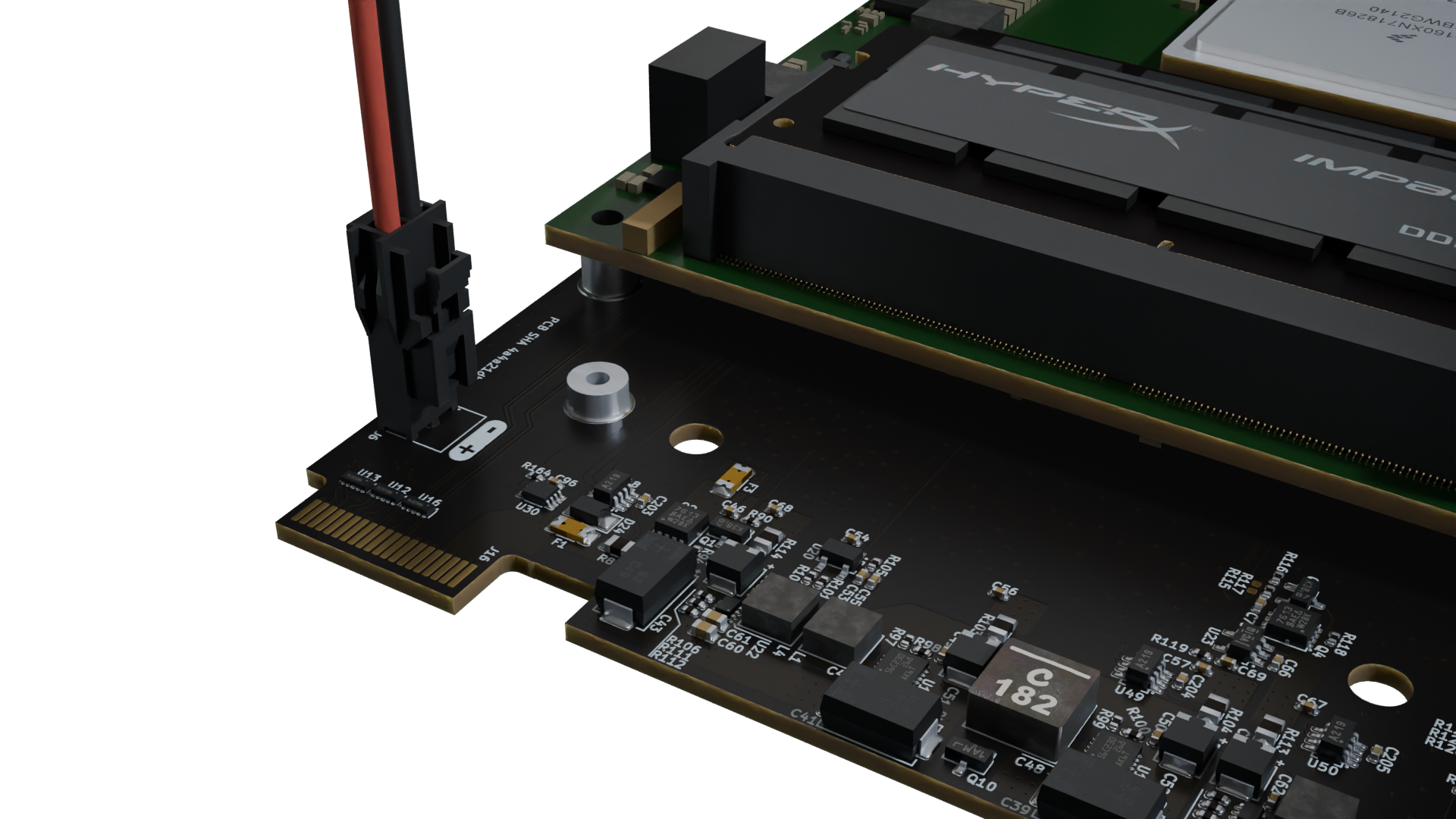
Figure 5 COM Express 7 Baseboard DC power connection with polarity marking (red: VCC, black: GND).
Backplane PCB-edge connector(J16) is designed to interface withSamtec HSEC8 2x20 HSEC8-120-01-S-D-EM2female connector. This connector has the same electrical requirements as the DC locking connector, since they are directly connected with each other on the baseboard. See the Pinouts section for the connector pinout.
These inputs are protected with a 12A fuse and 15V TVS diode. The nominal supply voltage is 12V. When LX2160A is used, absolute maximum is 15V and it requires 50W full system.
Auto startup
J7 jumper determines if auto startup is on/off.
When auto startup is enabled, all power rails of the COM Express 7 Baseboard turn on automatically after power is provided to the baseboard, and the SoM boots.
If auto startup is off, only the always on (AON) rails turn on after power is provided to the baseboard.
Then to continue the power up, power button SW1 needs to be pressed.
Power sequence
graph LR
V_IN --> +12V_AON --> +5V_AON --> +3V3_AON --> Power_button/auto_startup -->  +12V --> +5V --> +3V3 --> +1V8 --> +1V0 -->|120ms| PWR_OK
When 12V is supplied to the baseboard, LED
D18glows red, indicating that power is connectedAfter all power supplies start-up correctly, 1V0 rail will trigger
PWR_OKline to set to high state after 120ms (the delay is created byU20). This will result in (D18) changing color from red to green, which signals successful power supply section startup.There is a combinational logic circuit which pulls the
PSONnet low, if the COM Express module is NOT type 7. It is determined by the state of!TYPE0,!TYPE1and!TYPE2signals, which come from the connected COM Express module (pins C54, C57 and D57 ofJ12). This will prevent the baseboard from powering up, if wrong type of COM Express module is connected.
Power indicator LEDs
There are power indicator LEDs for every power rail (D26, D27, D28, D30, D31, D32, D33 and D34) as shown on the render below.
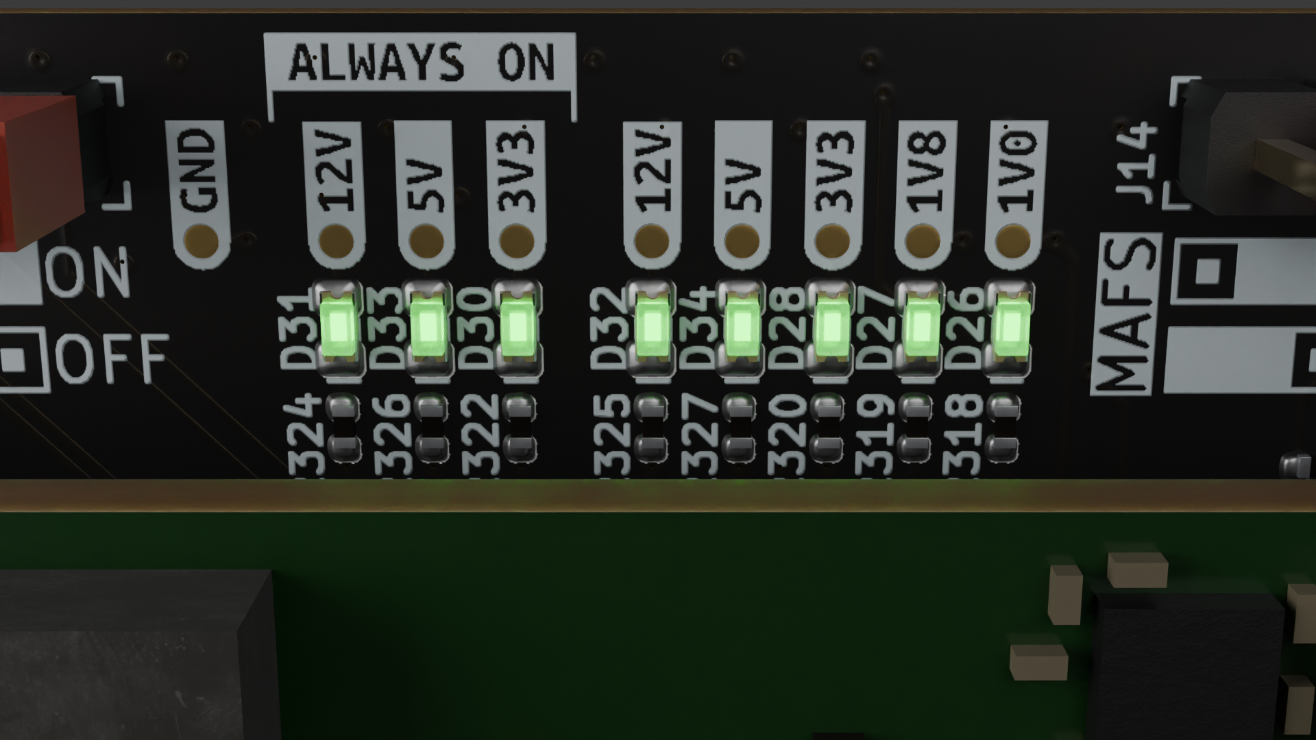
Figure 6 COM Express 7 Baseboard power indicator LEDs.
Supply monitoring
Three
INA219AIDCNRICs are used to monitor voltage and current draw on12Vinput,3V3and5Vrails. They are connected to I2Cbus 1of the SoM. Their I2C addresses and corresponding power rails are listed below:Address
Description
0x40
12V rail
0x41
3V3 rail
0x42
5V rail
ADT7476AARQZIC is used to monitor voltage of1V0,1V8,3V3,5V0and12Vrails. It is also connected to I2Cbus 1of the SoM, and its address is0x2D. The voltage readings can be accessed through the following register addresses:Register
Description
0x20
1V0 reading
0x21
1V8 reading
0x22
3V3 reading
0x23
5V reading
0x24
12V reading