Introduction
The Baseboard supports COM Express Type 7 modules. The board breaks out major communications and peripheral interfaces as defined by the COM Express standard. It features front panel connectors for cable interfaces and a backplane edge connector designed for integrating the board into larger systems.
One of the supported COM Express Type 7 modules is the SolidRun LX2160A. It features 16 Arm Cortex-A72 processors, 4 x 10GbE and 18x PCIe Gen 3.0 lanes and is fully supported by Linux.
The board design files were created in KiCad 8.x.
You can find out more about the COM Express 7 Baseboard by visiting Antmicro’s portals listed below:
They provide 3D renders and the board stackup definition, as well as an interactive preview of the board schematic. A PDF schematic of the board is also available.
Block diagram
IO map
A map of on-board connectors, status LEDs, control buttons and I/O interfaces is provided below.
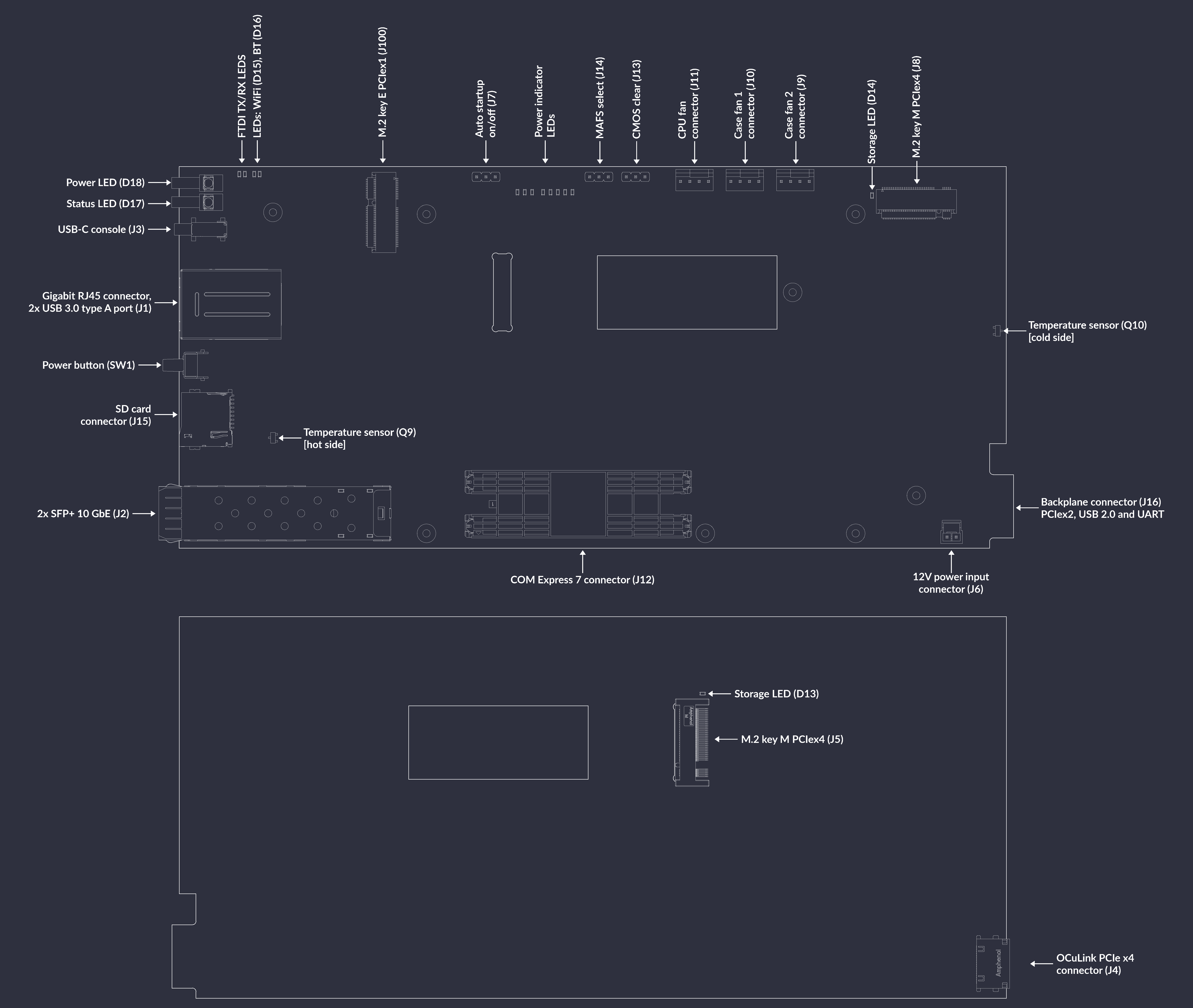
Figure 1 COM Express 7 Baseboard interface map
Power
COM Express 7 Baseboard can be powered with a DC voltage via the on-board locking DC connector (J6) with Molex Nano-Fit plug, or backplane PCB-edge connector (J16).
More details in Power supply section.
Available interfaces and features
2x SFP+ 10 Gigabit Ethernet port (
J2)Gigabit Ethernet RJ45 connector (
J1A)OCuLink PCIe x4 connector (
J4)USB-C console (
J3)M.2 2230 key E connector with PCIe x1 and USB (
J100)Backplane PCB edge connector (
J16) with PCIe x2, USB 2.0, UART console and 1x GPIOSD card connector (
J15)Board EEPROM and support for carrier MAFS BIOS
Power button (
SW1)Board temperature sensors (
Q9) and (Q10)2x RGB LED for status indication
Mechanics
The COM Express 7 Baseboard PCB is 227.5x104.0 millimeters (WxL) which translates into 8.96x4.09 inch.
The overall height of the set depends on the attached cooling module.