Advanced options
This chapter builds upon the content covered in the Getting started chapter. If you have not yet reviewed it, we recommend doing so before proceeding.
Creating block designs in the GUI
Upon successfully connecting to the server, Topwrap will generate and transmit a specification describing the structure of the selected IP cores. If the -d option is specified, the design will be displayed in the GUI. The following content is based on the PWM example located in examples/pwm. From this point, you can create or modify designs by:
adjusting the parameter values of IP cores. Each node includes input fields where you can specify parameter values (default values are automatically assigned when an IP core is added to the block design):
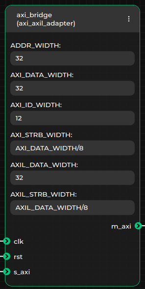
Parameter values can be specified as integers in various bases (e.g., 0x28, 40, or 0b101000) or as arithmetic expressions, which will be evaluated later (e.g., (AXI_DATA_WIDTH + 1) / 4 is a valid expression, provided a parameter named AXI_DATA_WIDTH exists in the same IP core). Additionally, parameter values can be written in Verilog format (e.g., 8'b00011111 or 8'h1F), in which case they will be interpreted as fixed-width bit vectors
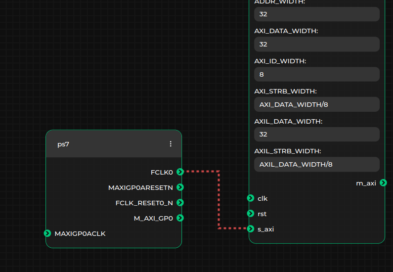
connecting the ports and interfaces of IP cores. Only connections between ports or interfaces of matching types are allowed. This is automatically validated by the GUI, which uses the type information from the loaded specification. As a result, the GUI will prevent users from making invalid connections (e.g., connecting
AXI4withAXI4Lite, or connecting a port to an interface). A green line will indicate a valid connection, while a red line will indicate an invalid one:
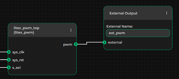
specifying external ports or interfaces in the top module. To do this, add the appropriate
External Input,External Output, orExternal Inoutmetanodes, and establish connections between these metanodes and the desired ports or interfaces. Ensure that the name of the external port or interface is updated in the textbox within the selected metanode. For example, in the case where the output pwm port of thelitex_pwm_topIP core is external to the generated top module, the external port name should be set toext_pwm, as shown below:
An example block design in the Topwrap GUI for the PWM project may look like this:
Important
With each graph change, Topwrap will save the current dataflow to ensure it’s not lost, e.g. during an accidental page refresh.
The file is located at $XDG_DATA_HOME/topwrap/dataflow_latest_save.json.
More information about this example can be found here