Getting started
The purpose of this chapter is to provide a step by step guide on how to create a simple design with Topwrap. All the necessary files needed to follow this guide are in the examples/getting_started_demo directory.
Important
If you haven’t installed Topwrap yet, go to the Installation chapter.
Design overview
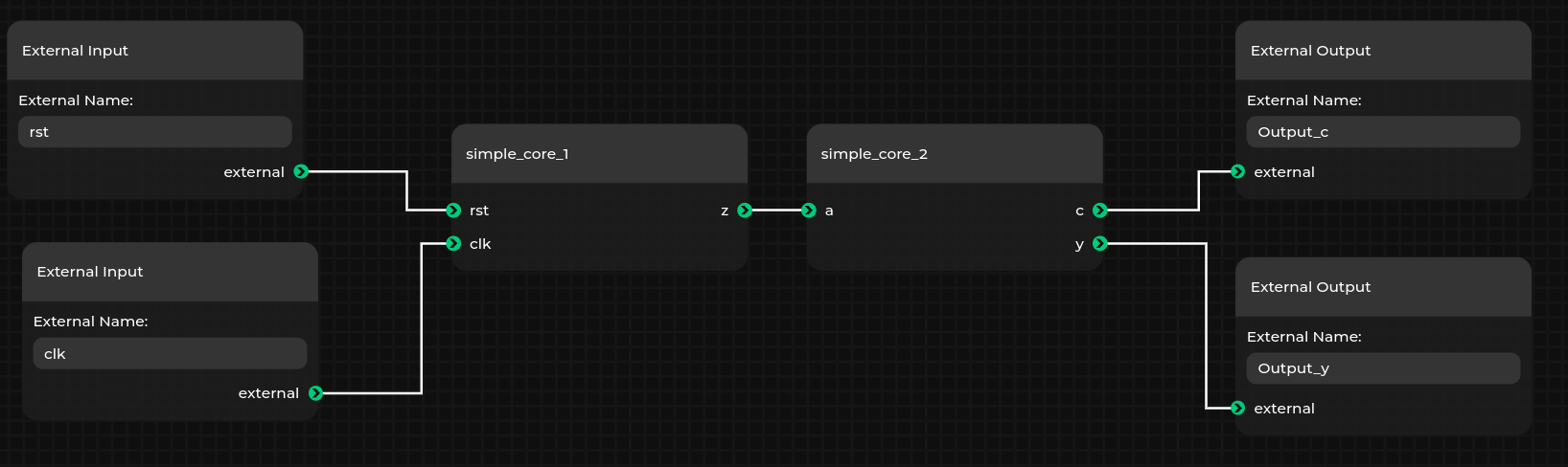
We are going to create a design that will be visually represented in an interactive GUI, as seen below.
It consists of two cores: simple_core_1 and simple_core_2 that connect to each other and to an external input/output.
Note
Metanodes are always utilized in designs to represent external input/output ports, module hierarchy ports or constant values. They can be found in the “Metanode” section.
Adding Verilog sources to repository
The verilogs directory contains two Verilog files, simple_core_1.v and simple_core_2.v.
In order to use external IP cores in a Topwrap design, they need to be added to a repository first.
The repository could either be created manually, or in an easier way, through CLI commands:
# To initialize an empty repository `my_repo_name` in `my_repo` directory
topwrap repo init my_repo_name my_repo

# To automatically parse all supported HDL sources from the `verilogs` directory
# and copy them to the previously created `my_repo` repository
topwrap repo parse my_repo_name verilogs
The topwrap repo init command will add the newly created repository to the project configuration file or create one if it’s missing.
Thanks to this, the repository will be automatically loaded by Topwrap in further commands.
Additionally, Topwrap supports adding interfaces to modules based on mapping files, and automatically generating mapping files when parsing sources. For more details, see the Interface mapping and inference page.
Building designs with Topwrap
Creating the design
The previously parsed source files can be loaded into the GUI with:
topwrap gui
The loaded IP cores can be found in the IPcore section:
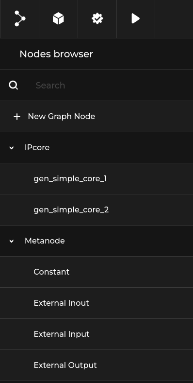
With these IP cores and default metanodes, you can easily create designs by dragging and connecting cores.
Let’s make the design from the demo in the introduction.
Note
You can change the name of an individual node by right clicking on it and selecting rename. This is useful when creating multiple instances of the same IP core.
You can save the design using the Save graph file option from the menu.
This will create a graph JSON format file used by the GUI.
This is essentially a snapshot of everything that you created in the editor and can be loaded back later.
Generating Verilog in the GUI
You can generate Verilog from the design created in the previous section if you have the example running as described in the previous section. On the top bar, these four buttons are visible:
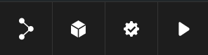
Save/Load designs.
Toggle the node browser.
Validate the design.
Build the design. If it does not contain errors, a top module will be created in the directory where
topwrap guiwas run.
Command-line flow
Creating designs
The manual creation of designs requires familiarity with the Design Description format.
First, include all the IP core files needed in the ips section.
ips:
  simple_core_1:
    file: repo[my_repo]:simple_core_1
  simple_core_2:
    file: repo[my_repo]:simple_core_2
Here, simple_core_1 and simple_core_2 are given instance names for IP cores loaded from the my_repo repository.
Now we can start creating the design under the design section. The design doesn’t have any parameters set, so we can skip this part and go straight into the ports section. In there, the connections between IP cores are defined. In the demo example, there is only one connection - between simple_core_1 and simple_core_2.
In our design, it is represented like this:
connections:
  ports:
    simple_core_2:
      a: [simple_core_1, z]
All that is left to do is to declare external ports, like this:
external:
  ports:
    in:
      - rst
      - clk
    out:
      - Output_y
      - Output_c
Now connect them to IP cores.
connections:
  ports:
    simple_core_1:
      clk: clk
      rst: rst
    simple_core_2:
      a: [simple_core_1, z]
      c: Output_c
      y: Output_y
The final design:
ips:
  simple_core_1:
    file: repo[my_repo]:simple_core_1
  simple_core_2:
    file: repo[my_repo]:simple_core_2
connections:
  ports:
    simple_core_1:
      clk: clk
      rst: rst
    simple_core_2:
      a: [simple_core_1, z]
      c: Output_c
      y: Output_y
external:
  ports:
    in:
      - rst
      - clk
    out:
      - Output_y
      - Output_c
Generating Verilog top files
To generate the top file, use topwrap build and provide the design. To do this, ensure you are in the examples/getting_started_demo directory and run:
topwrap build --design {design_name.yaml}
Where {design_name.yaml} is the design saved at the end of the previous section. This will generate a top.v Verilog top wrapper in the specified build directory (./build by default).
Synthesis & FuseSoC
You can additionally generate a FuseSoC core file during topwrap build to automate further synthesis and implementation by simply adding the -f (--fuse) option.
Logging
Topwrap uses Python’s built-in logging module. By default, logging is configured with the WARNING level.
The default can be changed using the --log-level option:
topwrap --log-level DEBUG build --design {design_name.yaml}